Improper pipe support acts as a silent saboteur in commercial facilities. It routinely triggers failed fire marshal inspections and causes catastrophic pipe breaks in modern installations. When contractors ignore strict spacing guidelines, they invite severe consequences. Non-compliance quickly leads to expensive rework delays and localized stress fractures. Furthermore, these failures create massive life-safety liabilities if sprinkler systems fail during emergencies.
This comprehensive guide establishes the critical engineering criteria for spacing your supports correctly. We compare metallic versus non-metallic piping requirements to keep you compliant across different environments. You will also learn a practical framework for selecting the best hardware for commercial procurement, ensuring a secure and highly reliable mechanical infrastructure.
Key Takeaways
NFPA 13 dictates maximum spacing distances, but system pressures, pipe materials, and seismic zones often require tighter spacing intervals.
Material dictates span: Steel and copper allow significantly longer hanger spans than nonmetallic pipes (like CPVC), which require closer support to prevent bowing.
Selection dictates performance: Choosing between a Clevis Pipe Hanger and a Swivel Pipe Hanger depends on load requirements, pipe trajectory, and seismic flexibility needs.
Regional codes matter: Local jurisdictions (e.g., NYC Building Code) frequently enforce stricter support criteria than baseline national standards.
The Engineering & Compliance Baseline for Hanger Spacing
Proper mechanical support relies heavily on established national standards. We look to NFPA 13 as the foundational rulebook for fire sprinkler support. This standard carefully defines the maximum allowable distances between structural supports. Its primary goal is to prevent dangerous structural deflection. When engineers ignore these baseline rules, they compromise the entire fire protection grid.
You must understand the basic physics of pipe sag to appreciate these rules. Gravity constantly pulls down on water-filled networks. Unsupported spans bow in the middle under this continuous weight. This bowing action creates severe stress concentrations at threaded joints and grooved fittings. Over time, these localized pressure points risk slow leaks or catastrophic system breaks. A sudden pressure surge during a pump activation can easily shatter a stressed joint.
To combat this, the industry utilizes strict baseline spacing expectations for general steel piping. Contractors can typically space supports up to 15 feet apart for standard steel branches. However, you must scale this distance down based on the pipe diameter. Smaller pipes lack the internal rigidity of larger mains. They require tighter intervals to maintain their linear integrity.
While NFPA codes provide an excellent baseline, they do not hold absolute authority everywhere. Local jurisdictions frequently overrule baseline national standards. The New York City Building Code enforces highly stringent support criteria for high-rise environments. Similarly, California mandates rigorous seismic sway bracing above and beyond standard requirements. You must always verify local code variances before finalizing your installation drawings.
Pipe Material Considerations: Metallic vs. Nonmetallic Support Limits
Material composition dictates how a system behaves under pressure. You cannot treat steel, copper, and plastic identically when designing your support infrastructure.
Metallic Pipe (Steel & Copper)
Metallic pipes boast incredibly high structural rigidity. This inherent strength allows for maximum span lengths across commercial ceilings. Steel resists deflection exceptionally well, even when fully pressurized. Copper also provides robust stability for standard plumbing and specialized sprinkler runs.
However, you cannot space metallic supports indefinitely. You must carefully factor water weight and pipe schedule into your total load calculation. A schedule 40 steel pipe carries significantly more dead weight than a schedule 10 pipe. Heavy-wall pipes increase the gravitational pull on your ceiling anchors. Always consult your structural engineer to verify the roof deck can handle these concentrated loads.
Nonmetallic Pipe (CPVC & Plastics)
Nonmetallic systems require an entirely different engineering approach. We use distinct spacing tables for CPVC and other plastic piping. You must follow these specialized charts strictly to maintain your system warranty.
Nonmetallic lines remain highly vulnerable to thermal expansion and sagging. Plastics soften and expand when exposed to high ambient temperatures. This material behavior requires significantly reduced spacing intervals. Installers often place supports every 5 to 6 feet, depending on the specific diameter. If you stretch this distance, the plastic will bow noticeably.
Furthermore, plastic systems require specific surge-restraint mechanisms. Sudden changes in water velocity create violent hydraulic shocks. These shocks can easily snap unsupported plastic branches. We install specialized restraints to prevent this dangerous whipping action.
Table 1: General Maximum Spacing Estimates by Material Type
Pipe Material
Typical Diameter
Estimated Max Span (Standard Conditions)
Steel (Schedule 40)
1 inch to 1.25 inch
12 feet
Steel (Schedule 40)
1.5 inch and larger
15 feet
Copper Tube (Type K/L)
1 inch to 1.25 inch
8 to 10 feet
CPVC (Nonmetallic)
1 inch
6 feet
CPVC (Nonmetallic)
2 inch and larger
7 to 8 feet
Evaluating Hardware: Clevis Pipe Hanger vs. Swivel Pipe Hanger
Selecting the proper hardware requires careful operational analysis. You must match the hanger geometry to your specific system demands.
Clevis Pipe Hanger
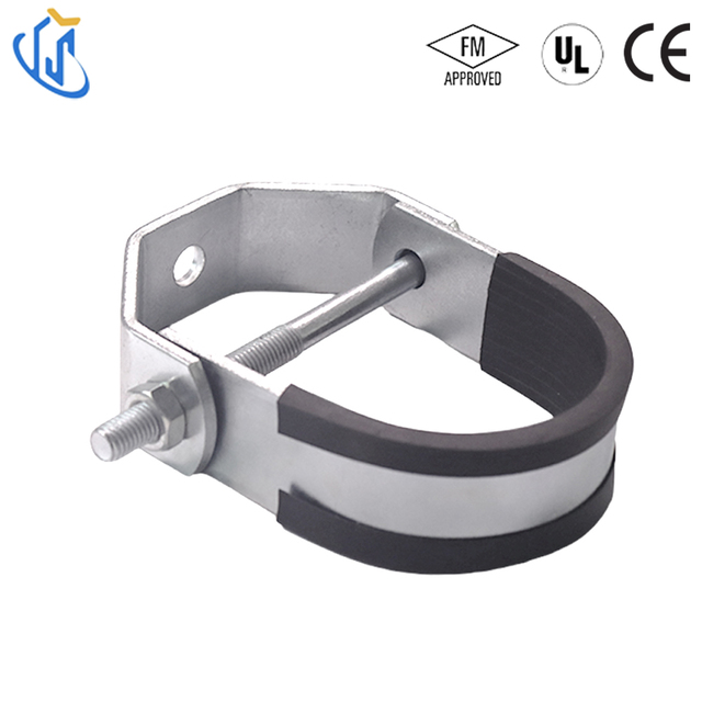
The Clevis Pipe Hanger serves as a workhorse in commercial MEP installations. It features a distinctive U-shaped lower strap suspended by an adjustable vertical rod. A heavy-duty cross bolt secures the pipe within the saddle.
We consider it the best use case for supporting heavy, horizontal runs of suspended stationary pipes. It excels on large main lines spanning long corridors. The evaluation criteria heavily favor its high load capacity. Installers appreciate the ability to make precise vertical elevation adjustments post-installation. You simply turn the upper and lower nuts to level the pipe perfectly. However, this rigid design offers limited lateral flexibility. It does not swing freely if the building sways.
Swivel Pipe Hanger
The Swivel Pipe Hanger solves a different set of engineering challenges. It features a specialized swivel joint located at the top connection. This joint allows crucial movement and dynamic angle alignment during installation.
We deploy this hardware predominantly for fire sprinkler branch lines. It represents the best use case for environments prone to vibration or active seismic zones. When evaluating its performance, we note how well it absorbs dynamic system shifts. It accommodates minor thermal expansion efficiently, preventing rigid stress fractures. While it offers superior flexibility, its maximum load capacities may differ from heavy-duty clevis options. Always verify the weight rating before hanging large mains.
Hardware Shortlisting Logic
You must base your final hardware selection on the actual operational environment. Differentiate between static loads and dynamic loads. Consider the total weight of water-filled lines. Finally, evaluate the adjustment requirements needed during the MEP rollout phase. Complex ceilings often require the flexibility of swivel options, while straight industrial runs benefit from rigid clevis supports.
Implementation Risks and Installation Realities
Theoretical engineering only works if field teams execute the installation correctly. Site walks frequently reveal serious implementation risks.
Galvanic Corrosion: You must guard against mixing incompatible metals. Hanging bare copper pipe on raw steel hardware triggers rapid material degradation. Moisture in the air acts as an electrolyte. This causes the copper to pit and eventually leak. Always use a proper isolator, or specify copper-plated hardware for these specific runs.
Overtightening and Friction: Installers routinely overtighten fasteners. This restricts natural thermal expansion. Nonmetallic lines require freedom to move. Pipes must be allowed to slide smoothly through the hanger ring as temperatures fluctuate. Binding the pipe creates immense internal stress.
Structural Attachment Integrity: A support device is only as reliable as its anchor point. Fastening a heavy-duty saddle to weak concrete accomplishes nothing. You must verify roof deck or concrete ceiling load capacities before drilling. Engage a structural engineer to confirm the substrate can handle the anticipated dead loads.
Inspection Red Flags: Fire marshals actively look for specific failures. Missing supports near end-line sprinklers represent a major violation. Improper rod sizing instantly flags a poor installation. Undocumented field modifications, like bending rods or cutting straps, will halt your project immediately.
Following strict installation protocols prevents costly rework. Train your field teams to recognize these specific red flags before the official inspection begins.
Procurement Criteria for MEP & Fire Protection Systems
Procuring reliable hardware requires more than just finding the lowest price. You must evaluate strict technical and logistical criteria before issuing a purchase order for Pipe Hangers.
Certifications
You cannot compromise on life-safety certifications. All fire protection hardware must be UL Listed and FM Approved. These markings prove the product survived rigorous tensile and vibration testing. Uncertified hardware introduces immediate liability. If an unlisted component fails during a fire, the legal and financial repercussions are devastating.
Material & Finish
Evaluate your corrosion resistance needs carefully. We select finishes based entirely on environmental exposure. Climate-controlled indoor offices typically accept standard electro-galvanized finishes. However, open parking garages face severe humidity and exhaust fumes. These harsh environments demand hot-dip galvanized or specialized epoxy-coated options. Choosing the wrong finish guarantees premature rust and eventual structural failure.
Vendor Scalability and Lead Times
Large commercial projects consume thousands of support brackets. You must assess the supplier's ability to deliver consistent bulk quantities. Batch variations in thread quality or steel thickness cause massive installation delays. Your vendor must maintain predictable lead times. Reliable logistics are absolutely critical for maintaining project timelines on large-scale commercial jobs.
Next-Step Action
Do not guess on your procurement needs. We recommend engaging directly with structural engineers immediately. Run localized load calculations before executing any bulk purchasing agreements. Verify your selected hardware matches the specific environmental demands of your facility. Contact verified suppliers to secure certified technical datasheets for every component.
Conclusion
Spacing your structural supports is a calculated engineering requirement, not a casual installation guideline. Properly designed mechanical infrastructure protects your facility from catastrophic leaks and premature wear. When you respect the physics of fluid weight and thermal expansion, your piping networks perform flawlessly for decades.
The combination of accurate spacing, appropriate material matching, and certified hardware ensures long-term system reliability. Whether you select rigid clevis components or flexible swivel joints, you must align the hardware with the operational environment. Doing so guarantees compliant, stress-free fire marshal walk-throughs.
Take proactive steps today to secure your MEP systems. Review your current project submittals against the latest NFPA tables. Contact a certified manufacturer to request verified hardware load datasheets before you begin your next major installation.
FAQ
Q: Is a pipe hanger required on every single sprinkler pipe segment?
A: No. While it seems logical, NFPA 13 includes specific exceptions. Certain short branch lines or arm-overs may not require independent hangers. If the main structure supports the adjacent pipe within a specific allowed distance, you can skip a dedicated support on that short segment. Always check the exact length limits in the code.
Q: Can I use the same pipe hangers for plumbing and fire sprinkler systems?
A: Not necessarily. Fire sprinkler hardware requires strict UL/FM approvals. Engineers design these specific components to handle sudden, high-pressure surge loads during pump activations. Standard plumbing supports may lack the tensile strength necessary to meet these extreme life-safety stress tests.
Q: How does seismic activity impact hanger spacing and selection?
A: Seismic zones require significantly tighter design controls. You must install supplementary sway bracing to absorb violent lateral and longitudinal forces. Furthermore, contractors utilize flexible hardware configurations, like swivel joints, to prevent rigid snapping. These dynamic requirements often reduce the standard allowed spacing intervals considerably.
Utterly TY Intelligent Technology Co.,Ltd. is a high-tech private enterprise integrating product design, research and development, sales and installation.