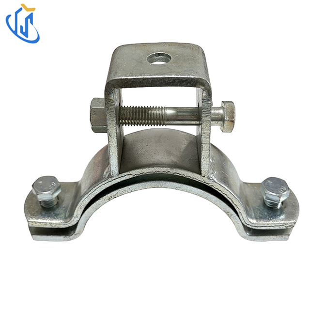
A pipe support system is only as reliable as its weakest fastening point. Incorrect specification often leads to localized pipe stress, severe structural damage, or catastrophic failure during sudden pressure surges. A pipe clamp goes far beyond merely bearing static weight within a facility. It is engineered to transfer dynamic loads safely, manage complex thermal movement, and actively isolate vibration between the piping network and the primary building structure. Ignoring these forces puts your entire facility layout at risk. This guide breaks down the underlying mechanical principles of modern pipe clamps. We will explore categorization frameworks for precise structural specification and outline robust risk mitigation strategies for decision-makers and system architects. By the end, you will understand exactly how to align clamping configurations with your specific routing environments to ensure long-term structural integrity.
Key Takeaways
Dynamic Load Management: Pipe clamps actively manage physical stresses, including thermal expansion, hydrostatic pressure changes, and acoustic vibration, not just dead weight.
Application-Specific Selection: Routing geometry dictates clamp selection, requiring distinct configurations like a suspension pipe clamp for horizontal ceilings or a riser pipe clamp for vertical floor penetrations.
Compliance and Scalability: Procurement must balance structural safety factors with environmental variables, heavily factoring in corrosion resistance and specialized bracing like a seismic sway clamp for code compliance.
The Functional Role of a Pipe Clamp in System Integrity
Unmanaged piping forces cause serious structural issues over time. They result in premature component wear, joint leaks, and warranty invalidation. The clamp serves as the critical interface protecting both the pipe and the surrounding structure. It bridges the gap between the fluid conveyance network and the building frame. System architects must understand how these components absorb and redirect force.
Load Transfer Mechanics (Dead vs. Live Loads)
Clamps must bear multiple types of stress simultaneously. We categorize these into static and dynamic forces. Managing both is crucial for system reliability.
Dead Loads: These represent the continuous, static weight of the pipe itself. They also include the weight of the fluid inside, external insulation, and any integrated valves. Clamps transfer this downward force into load-bearing beams or concrete slabs.
Live Loads: These are unpredictable, dynamic forces. They arise from sudden flow changes, known as water hammer, or external environmental shifts. Clamps must resist these sudden spikes in kinetic energy to prevent the pipe from tearing away from its mounts.
Thermal Expansion and Contraction
Metal and plastic pipes expand when heated and contract when cooled. You cannot simply lock a pipe in place and ignore thermodynamics. Planners must differentiate between clamps used as rigid anchors and those used as guides.
Rigid anchors clamp down tightly onto the pipe exterior. They prevent all movement in the X, Y, and Z axes. We use anchors to force thermal expansion into specific, planned directions. Conversely, guide clamps wrap loosely around the pipe. They restrict lateral and vertical movement but allow the pipe to slide longitudinally. This deliberate sliding motion prevents dangerous buckling along long pipe runs.
Acoustic and Vibration Isolation
Pumps and fast-moving fluids generate significant mechanical vibration. If left unchecked, this high-frequency vibration transfers directly into the building structure. It causes noise complaints and loosens nearby structural fasteners over time.
Manufacturers integrate elastomeric linings, such as EPDM rubber, into the clamp body. This rubber dampens the vibration before it reaches the mounting hardware. Furthermore, the rubber lining acts as a crucial dielectric barrier. It prevents galvanic corrosion between dissimilar metals, such as a copper pipe resting inside a galvanized steel clamp.
Aligning Clamp Configurations with Structural Routing Environments
Evaluating the physical routing dictates your structural approach. No single clamp design fits every orientation. Engineers must match the mechanical mechanism of the clamp to the geometric reality of the installation space. Selecting the wrong configuration creates hazardous stress points.
Horizontal Overhead Routing
Many facilities run utilities high above the floor to save space. A Suspension Pipe Clamp perfectly suits this environment. Its mechanism utilizes threaded rods to hang horizontal pipe runs directly from ceilings or structural I-beams. We evaluate this option as best for gravity-fed drainage systems or overhead utility lines. However, engineers must carefully evaluate the pendulum effect. Long threaded rod drops can sway excessively if lateral bracing is absent. This sway creates fatigue at the upper mounting point.
Vertical Floor Penetrations
Multi-story buildings require fluid to travel vertically through floors. A Riser Pipe Clamp provides the necessary support for these drops. Its mechanism grips vertical piping tightly. It utilizes wide shear lugs or ears that rest directly on the floor penetration. This design transfers the massive vertical load directly into the heavy concrete slab. When evaluating this clamp, success hinges entirely on friction coefficients and structural shear strength. The bolts must be torqued precisely to prevent the heavy pipe from slipping downward through the clamp body.
Parallel Multi-Pipe Routing
Industrial spaces frequently run multiple pipes alongside one another. A Channel Mount Clamp simplifies this complex layout. Its mechanism relies on two-piece clamps designed to lock directly into standard metal framing, often called strut channels. We evaluate this as highly scalable. It enables rapid installation for parallel runs. Furthermore, it allows maintenance teams to execute future retrofitting without heavy, hazardous welding. You simply twist a new clamp into the existing channel track.
Performance Criteria for Specification and Procurement
Procurement teams must move beyond simple unit cost. They need to evaluate total lifecycle reliability. A cheap clamp failing in a critical system causes severe downtime. Proper specification requires assessing materials, load limits, and temperature thresholds.
Material Selection and Corrosion Risk
You must assess the clamp material against the operating environment. Plain carbon steel works well in dry, indoor environments. However, it rusts quickly when exposed to moisture. Hot-dipped galvanized finishes provide a robust zinc coating, offering excellent protection for standard outdoor or humid settings. For extreme environments, such as chemical processing plants or coastal facilities facing saltwater spray, stainless steel (304 or 316 grades) becomes mandatory.
Material Selection vs Operating Environment Chart
Material Type
Corrosion Resistance
Ideal Operating Environment
Common Risk Factors
Standard Carbon Steel
Low
Indoor, climate-controlled spaces
Rapid oxidation if exposed to high humidity
Hot-Dipped Galvanized
Medium-High
Outdoor, parking garages, industrial
Zinc layer degradation over decades
Stainless Steel (304/316)
Very High
Coastal, chemical, sanitary food grade
Galling of threaded fasteners during install
Load Ratings and Safety Factors
You must rigorously verify manufacturer technical datasheets. Every structural clamp carries a stated working load limit (WLL). This limit must mathematically exceed the maximum anticipated load of the pipe, fluid, and insulation combined.
Engineers do not stop at the exact weight limit. They factor in standard safety margins. Depending on local building codes and the criticality of the system, safety factors typically range from 3:1 to 5:1. A 5:1 safety factor means the clamp is tested to hold five times the stated WLL before experiencing mechanical failure. This buffer accounts for unexpected dynamic shifts.
Temperature Tolerances
Internal fluid temperatures directly impact external clamping hardware. Ensure both the metal alloy and any insulating rubber liners can withstand the maximum operating temperature. Standard EPDM rubber degrades or melts at extremely high temperatures, such as those found in steam piping. For high-heat applications, system architects specify specialized fiberglass inserts or silicone-based liners that maintain their structural integrity without degrading over time.
Mitigating High-Stakes Risks with a Seismic Sway Clamp
Standard dead-weight clamps are wholly insufficient for earthquake-prone zones. They also fail in highly volatile industrial environments where sudden mechanical shocks are frequent. In these high-stakes scenarios, compliance and facility security require specialized bracing.
The Role of Specialized Bracing
A standard hanger merely holds the pipe up. A Seismic Sway Clamp acts differently. It is designed specifically to resist violent lateral and longitudinal sway. During a seismic event, the ground moves independently of the suspended pipe mass. This generates immense kinetic energy. Sway clamps lock the pipe rigidly to the building structure at specific angles. This prevents the pipe from swinging, impacting adjacent structures, and ultimately shearing at the joints.
System Integration
Sway clamps do not operate in isolation. They integrate into a broader seismic bracing system. Installers use them alongside rigid steel bracing struts or heavy-duty aircraft cable restraints. Together, these components keep the pipe trajectory within safely engineered tolerances. They absorb the shockwaves and distribute the load safely into the primary building frame.
Verification and Code Compliance
You cannot assume a heavy bracket will survive an earthquake. Regulatory bodies require strict proof of performance. Planners face the absolute necessity of specifying components with explicit third-party approvals. Look for components that are UL listed or FM approved. These certifications guarantee the hardware has undergone rigorous physical stress testing. They are legally mandatory for fire protection systems and general seismic code compliance in many global jurisdictions.
Implementation Realities, Spacing, and Maintenance
Even perfectly specified clamps fail if installation assumptions are flawed. Theoretical engineering must align with on-site implementation realities. Small errors during installation multiply across miles of piping, leading to eventual structural fatigue.
Support Span Calculations
You must determine the correct distance between clamps. This distance is known as the support span. It relies heavily on the pipe material and fluid density. Rigid carbon steel pipes can bridge long gaps without drooping. Conversely, flexible PVC or PEX tubing requires clamps placed much closer together. Incorrectly spacing clamps leads to pipe sagging. Sagging creates low points where fluid pools, accelerating internal corrosion and disrupting flow dynamics. Installers usually follow MSS SP-58 spacing guidelines to ensure proper intervals.
Torque Precision
Fastening a clamp requires exact torque application. Relying on "feel" causes severe problems. There is a distinct risk of over-tightening. Applying too much torque causes pipe wall deformation, particularly in softer copper or plastic lines. It also crushes external insulation, destroying its thermal properties. Conversely, under-tightening the hardware is equally dangerous. Loose bolts lead to slippage. The pipe vibrates loosely within the clamp body, causing rapid friction wear and eventual rupture.
Installation Troubleshooting Matrix
Observed Issue
Probable Cause
Corrective Action
Pipe sliding through vertical support
Insufficient torque or low friction
Apply torque to spec; utilize friction tape or heavier shear lugs.
Squeaking or grinding noises
Thermal expansion binding at clamp
Switch from rigid anchor to a sliding guide clamp design.
Crushed foam insulation
Direct clamping over soft insulation
Install rigid insulation shield blocks before clamping.
Rapid rust on mounting bolts
Incorrect material specification
Replace carbon steel bolts with hot-dipped galvanized or 316 stainless.
Inspection Protocols
Installations require ongoing attention. Facility managers must establish strict maintenance routines. Over time, building vibrations cause fastener back-off, where nuts slowly unscrew themselves. Maintenance teams must check for this loosening during annual sweeps. They must also inspect elastomeric liners for dry rot or degradation. Finally, teams need to look for signs of structural fatigue, such as micro-cracking in the concrete, at high-stress anchoring points.
Conclusion
Securing a piping network demands rigorous attention to physical forces and spatial geometry. Base your final procurement decisions on a strict evaluation matrix. This matrix must account for maximum operating loads, harsh environmental conditions, specific spatial routing, and regional regulatory compliance requirements. Selecting hardware based solely on initial purchase price invites catastrophic system failure down the road.
Take proactive steps to ensure facility safety. First, consult with licensed structural engineers to perform custom load calculations for any critical infrastructure. Second, always request detailed manufacturer submittal packages to verify safety margins. Finally, integrate accurate 3D BIM (Building Information Modeling) objects of your chosen clamps into your software. This step validates physical fit and clash detection within the broader facility model before construction even begins.
FAQ
Q: How do you determine the correct size of a pipe clamp?
A: Sizing is based on the true Outer Diameter (OD) of the pipe, strictly accounting for any external insulation. Standard nominal pipe size (NPS) can be misleading. You must cross-reference the NPS with exact OD dimensions provided by the manufacturer to ensure a secure, gap-free fit.
Q: Can standard pipe clamps be used on insulated pipes?
A: Direct clamping inevitably crushes standard insulation. This creates harmful thermal bridges and localized condensation issues. Insulated pipes require dedicated load-bearing insulation blocks (often called inserts) or oversized clamps equipped with integrated rigid thermal shields to protect the foam.
Q: What is the difference between a guide clamp and an anchor clamp?
A: An anchor restricts movement in all three dimensions (X, Y, Z). It forcefully redirects thermal expansion elsewhere in the system. A guide clamp restricts lateral and vertical movement to prevent swaying, but it freely allows the pipe to slide longitudinally along its axis as temperatures change.
Utterly TY Intelligent Technology Co.,Ltd. is a high-tech private enterprise integrating product design, research and development, sales and installation.